

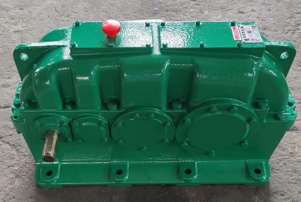
ZSY180-31.5-IV gear reducer for construction machinery with hard tooth surface cylindrical gear reducer
When installing ZSY180 reducer, the following are some precautions to improve installation accuracy:
Basic preparation
The installation foundation of the reducer should have sufficient rigidity and stability to withstand the load and vibration during the operation of the reducer. The basic surface should be flat, and the levelness error should be controlled within the specified range. Tools such as a spirit level can be used for measurement and adjustment to ensure that the basic levelness does not exceed 0.1mm per meter.
According to the installation dimension diagram of the reducer, accurately reserve anchor bolt holes on the foundation. The position and size of the hole should match the anchor bolt of the reducer, and the deviation should not exceed ± 2mm.
Gearbox inspection
Before installation, carefully inspect the appearance of the gearbox for any damage, bumps, or other defects, and ensure that all components are complete.
Check the size, shape, and surface quality of the output shaft and input shaft of the reducer to ensure no wear, deformation, or other defects. At the same time, the radial and end face runout of the measuring shaft should comply with the requirements of the equipment technical documents. Generally, the radial runout should not exceed 0.05mm and the end face runout should not exceed 0.03mm.
Check the inside of the gearbox of the reducer to ensure that the gears, bearings, and other components are securely installed, and that the amount of lubricating grease or oil meets the requirements.
Installation location determination
Determine the installation position of the reducer according to the process flow and layout requirements of the equipment. Ensure that the connection between the reducer and the driving equipment (such as motors) and the driven equipment (such as conveyor belts, mixers, etc.) is convenient, reasonable, and easy to operate, maintain, and repair.
Ensure that the installation position of the reducer is easy to install and disassemble, and there should be sufficient space around it. Generally, it is required to leave at least 0.5-1m of space around the reducer for inspection, refueling, maintenance and other operations.
Coupling installation
Choose a suitable coupling and ensure that it matches the input shaft of the gearbox and the output shaft of the drive motor. The type and specifications of the coupling should be determined based on the transmitted torque, speed, shaft diameter, and other parameters.
When installing the coupling, its coaxiality should be strictly controlled. Generally, tools such as a dial gauge are used for measurement and adjustment to ensure that the radial displacement of the coupling does not exceed 0.05-0.1mm and the angular displacement does not exceed 0.5 ° -1 °.
Installation of foundation bolts
Place the reducer on the foundation and thread the anchor bolts into the reserved holes on the foundation. Insert an appropriate thickness of adjusting shim between the bottom surface of the reducer and the foundation. Generally, the shim thickness is 20-50mm, and the number of shims per group should not exceed 3-5.
Use tools such as a level and dial gauge to preliminarily level and align the gearbox. Adjust the height and position of the shim to ensure that the levelness and position of the reducer meet the requirements. Then, pre tighten the anchor bolts with a uniform and moderate pre tightening force, usually 50% -70% of the bolt tightening force.
After the installation of the reducer is completed, tighten the anchor bolts again to the specified tightening torque. The tightening torque should be determined based on the specifications and materials of the anchor bolts, and can refer to relevant mechanical design manuals or equipment technical documents.