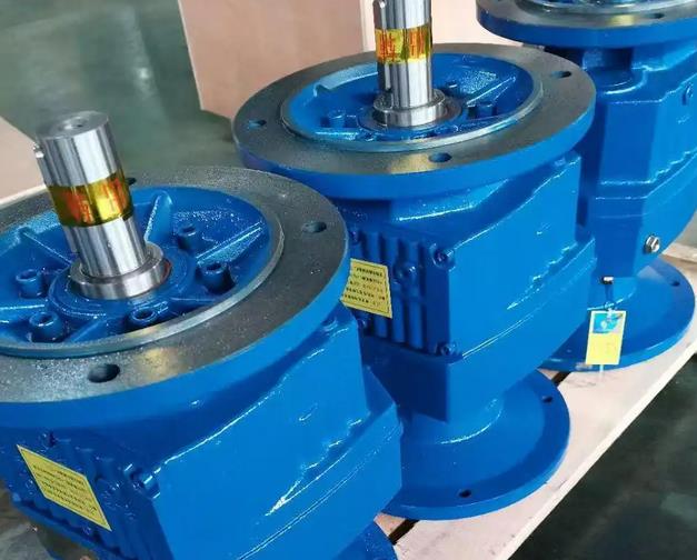
Correct usage of cycloidal pinwheel reducer in single-stage worm gear reducer
Many new customers who have just purchased single stage worm gear reducers often ask the editor about the usage methods of single stage worm gear reducers. In communication with customers, the editor found that some people do not understand the use of cycloidal pinwheels in single stage worm gear reducers. So today, let me tell you about the correct usage of cycloidal gear reducers in single stage worm gear reducers.
Cycloidal gear reducer is a new type of transmission machinery in the single-stage worm gear reducer industry, which has outstanding characteristics such as high reduction ratio, high transmission efficiency, small size, and light weight. Cycloidal gear reducer is widely used as a driving and reducing device in the fields of textile printing and dyeing, light industry and food, metallurgy and mining, petrochemicals, lifting transportation, and engineering machinery. For any machinery, only by mastering its correct usage method can its service life be better extended.
Worm gear reducer
1. The reducer is suitable for 24-hour continuous operation and allows forward and reverse operation.
2. In situations where overload may occur, overload protection devices should be installed.
3. The output shaft steering of a single stage reducer is opposite to the input shaft steering.
4. The output shaft of the gearbox cannot withstand significant axial force.
5. When using a coupling to connect the cycloidal gear reducer with the matching machinery, it is recommended to use an elastic coupling.
6. The foot plate horizontal mounted cycloidal pin wheel reducer must be installed on a vibration free and very sturdy horizontal foundation. In situations where inclined installation is necessary, the inclination of the axis of the cycloidal pin wheel single stage worm wheel reducer must not exceed ± 15.
7. The gearbox has no self-locking function.
8. In situations of high impact, vibration, or frequent starting, in addition to connecting the base and foundation with anchor bolts, positioning pins need to be used for fixation, and positioning pins need to be provided by oneself.
9. When installing a flange type vertical mounted cycloidal gear reducer, remember to keep the output shaft vertically downwards.
10. If other special installation forms other than foot plate horizontal installation and flange vertical installation are required, corresponding lubrication and sealing measures must be taken to ensure sufficient lubrication of the reducer to prevent oil leakage.
11. The installation angle of the cycloidal gear reducer lubricated with grease is free.
12. When using a sprocket for transmission, do not loosen the tooth chain too much, otherwise it is easy to generate impact force during starting.
13. The input shaft and output shaft of the standard cycloidal pinwheel reducer are cylindrical in extension and connected with ordinary flat keys.
14. When the reducer is connected to the matching machinery using a coupling, the coaxiality of the two axis lines shall not exceed the allowable range of the coupling.
15. When the cycloidal pinwheel reducer is connected to the gear and sprocket, it is necessary to ensure that the axis lines of the two are parallel.
16. When installing the gearbox, adjustment can be made using cushion blocks. The cushion blocks should not exceed three in the height direction, and can also be adjusted using wedges. However, after the gearbox is calibrated, it must be replaced with flat cushion blocks.
17. When connecting couplings, gears, sprockets, and other connecting parts to the output shaft of the cycloidal gear reducer, direct hammering is not allowed. Instead, the bolt should be screwed into the shaft extension end screw hole and pressed in through the pressure plate.
18. The installed reducer must undergo a test run before formal use. Under normal no-load operation, gradually load and operate again.


